
I recently met a 3rd officer. I had a conversation with him about less number of jobs these days for junior officers.
He told me how he got the job just after clearing his exams while his friends were still waiting.
You might ask what edge he had over his friends !!!
Well, he had worked on ships (tankers) with Framo pumps.
I was like.. what ?? Now Framo system helping to get the jobs on ships.
Few seconds later when I got my breath back, I realised how Framo has captured the tanker market.
Truth be told, Submersible pumps are the present and future of the tanker industry.
This makes the knowledge of Submersible pumps and Framo system so much important. This post is about the basics of the Framo pump so let’s start with that.
How a centrifugal pump works ?
Framo submersible pumps are centrifugal pumps. So before we discuss Framo pumps, we must know how a centrifugal pump works ?
And this video might help in understanding of how a centrifugal pump works.
I am not going in details of how a centrifugal pump works. But if you watch the above video, you would know that it has three main components
- Impeller
- Volute casing surrounding impeller, and
- A prime mover (source of energy) to move the impeller
Prime mover provides the energy for the impeller to rotate. Impeller rotates and pushes the liquid into the volute casing.
Volute casing has a spiral structure. It has narrow opening at the entry of liquid and the size of opening increases along the passage of liquid.
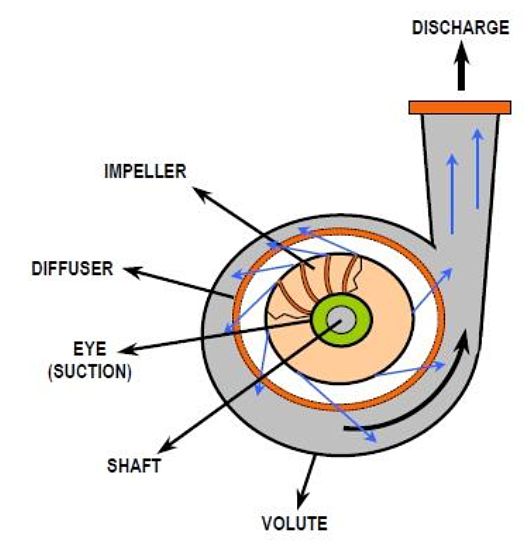
This means that as the liquid travels in the volute casing, velocity reduces and pressure increases. This is as per Bernoilli’s Theorum.
This is the most basic points we should know before we proceed with any kind of centrifugal pump.
Components of FRAMO system
As with all centrifugal pumps, Framo pump also have
- Impeller
- Volute casing
But apart from being a centrifugal pump, FRAMO is also a submersible pump. That is the pump is fitted inside the cargo tank and will be submerged in the liquid (cargo).
Keeping this in mind, let us discuss the components of FRAMO system to better understand this.
1. Hydraulic Motor
For the centrifugal pump to work, impeller need to rotate. But impeller would not rotate on its own. It need a source of energy (prime mover).
In steam turbine centrifugal pumps, this energy is provided by steam. For electric pumps, electric motor provides this energy for rotating the impeller.
In FRAMO system, this energy is provided by the Hydraulic motor using the pressurised hydraulic oil.
How ? Well we all have read the below law of conservation of energy. Haven’t we ?
“Energy can neither be created not destroyed. It can only be converted from one form to another”
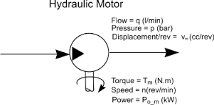
Hydraulic motor converts pressure energy of high hydraulic oil pressure to rotational energy to rotate the impeller.
Below diagram is the most basic diagram that shows how a hydraulic motor works.

High pressure oil enters the motor. It rotates the shaft and low pressure oil leaves the motor.
In Framo system, you will not be able to see the hydraulic motor as it is placed in the outer casing.
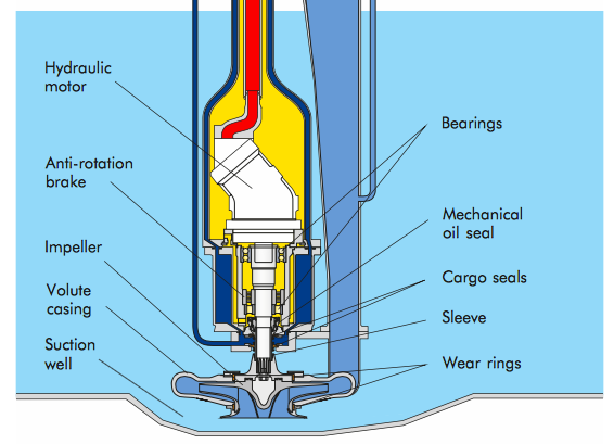
And there are no serviceable parts in a Framo hydraulic motor.
2. Power Packs
For the Hydraulic motor to rotate the impeller, there need to be high pressure of hydraulic oil.
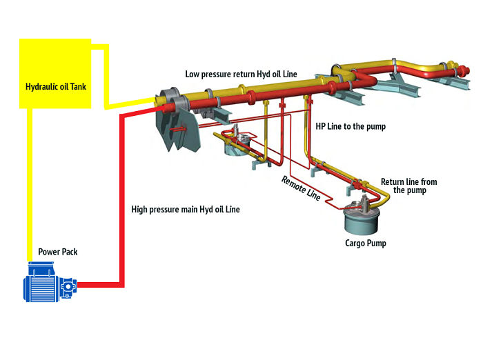
Power packs supply this high pressure hydraulic oil to the Framo hydraulic motor.
Power packs are either installed in the forecastle store or in the engine room of the ship.
Power pack system consists of
- A hydraulic oil tank to draw the oil from
- High pressure pump to take suction from the Hydraulic tanks and pump this oil into the hydraulic pipeline on deck
- Electric motor to run the High pressure pump
It is important that hydraulic oil tank always have sufficient oil for the high pressure pump. If it has less or no oil, the pump will get damaged.
Less or no oil can be because of two reasons.
- No oil in the tank
- Closed Suction valve to the power pack
There are two safe gaurds in the Framo system to ensure this.
- “Closed suction line” trip
- “Low oil level” trip
Closed suction valve trip
If the suction valve for the high pressure pump is closed, the power pack will trip. This ensures that the suction valve of the pump to take suction from hydraulic tank is not inadvertantly closed.
The alarm for the trip will display in cargo control room as well as Engine control room.
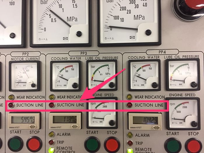
There is a sensor arrangement for the suction valve, which senses if the suction valve is fully open.
In old Framo system this could be a manual valve with its handle touching the sensor. If the suction valve is even slightly closed, its looses the touch of sensor and trip is activated.
In new systems, the valve is not a manual valves. In this case the a proximity sensor is fitted on top of the valve, that senses if the valve is fully open or not.
Low oil level trip
The power pack can loose suction if there isn’t sufficient oil in the hydraulic tank. For this reason when the oil level in the hydraulic tank goes below minimum level, the power pack will trip.
The oil level in the hydraulic tank is kept just above the alarm level. This ensures that any leakage in the line will be immediately detected without the loss of much of hydrualic oil.
There are two alarms for low level
- Low Level alarms, and
- Low Low level Alarm
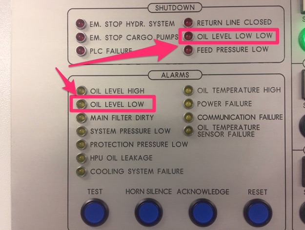
When the level is at Low level, an alarm will activate and will be displayed in CCR and ECR.
If the level of the oil further drops to “Low Low”, the hydraulic oil system (Power pack) will trip.
If the low oil level trip is activated, the reason for low level must be investigated. The oil can then be refilled either from the standby tank or spare drums whichever available.
It is important to fill only the correct grade of hydraulic oil.
3. Cofferdam and Purging routine
So far we have discussed that
- Framo pump is run by hydraulic motor and
- Hydraulic motor gets the pressurised hydraulic oil from the power packs
Now let us see the internal parts of the framo pump.
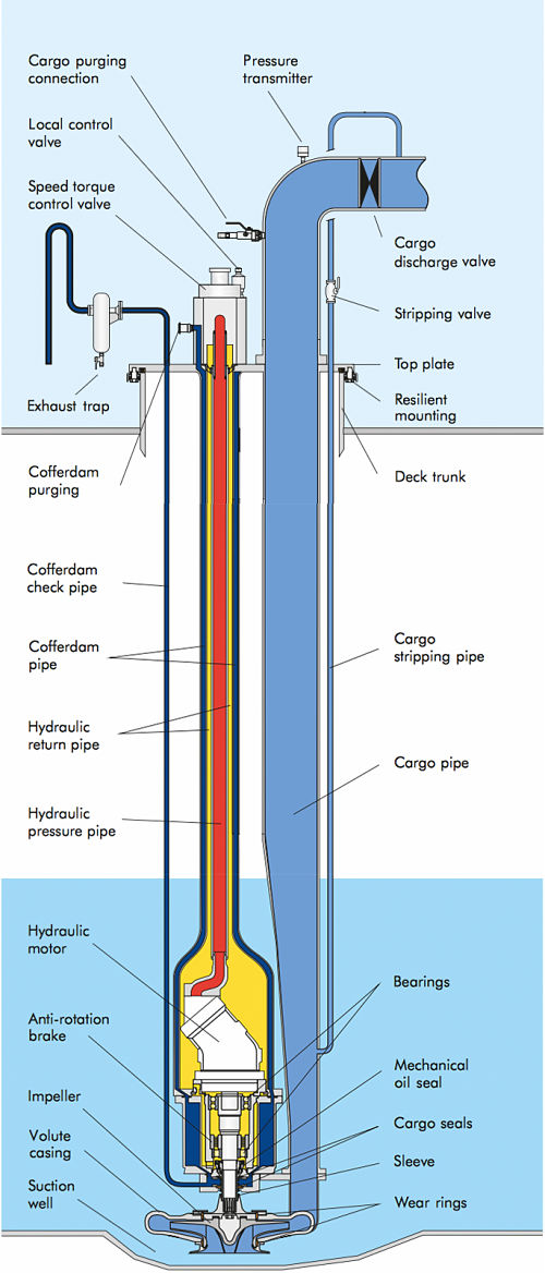
If you notice,
- the red section is the high pressure hydraulic oil going into the hydraulic motor.
- Yellow part is the hydraulic oil return.
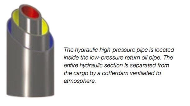
Both these pipes are concentric to each other. Like in below picture.
This pump is inside the cargo tank and there are two liquids (hydraulic oil and cargo) that should not come in contact.
If the hydraulic oil leak into the cargo, cargo can damage. If cargo goes into the hydraulic oil, the hydraulic system will damage.
As you might have guessed, there is something in the Framo pump to prevent that. There is hydraulic seal that prevents hydraulic oil leakage to the cargo side. And there is cargo seal that prevents cargo leaking into the hydraulic side.
But seals can leak overtime, right ? so if any of these seals are leaking, how would we know ?
That is exactly the purpose of cofferdam.
You can think of cofferdam as a steel cup with cargo seal at the bottom. Any hydraulic oil or cargo leakage will collect in this cofferdam.
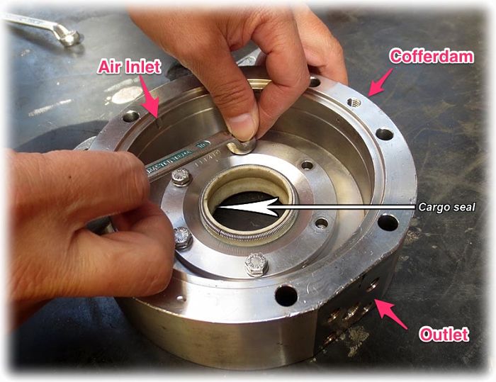
It is important to know if the cofferdam is empty or not. And this is done by purging the cofferdam.
We introduce air or nitrogen in the cofferdam and check the outlet of the purging line.
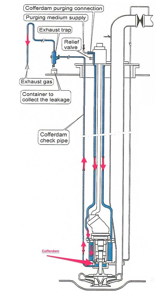
- If we just get the air in outlet of purging line, the cofferdam is empty. So no leakage of hydraulic oil or cargo and both the seals are intact.
- If we get cargo in the cofferdam, it indicates that the cargo seal of the Framo pump is leaking
- If we get Hydraulic oil in the cofferdam, it indicates that Hydraulic oil seal of the framo pump is leaking
- If we get mixture of Hydraulic oil and cargo, it indicates that both oil seal and cargo seal are leaking
If any of the seal is leaking, it need to be replaced with new seal after the discharging and tank cleaning of the tank.
Framo has a purging routine which shows when the purging of the pump cofferdam need to be carried out.
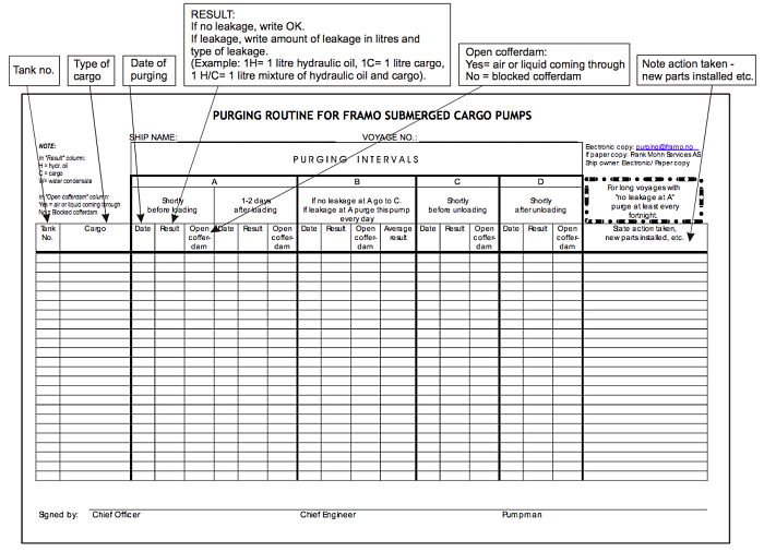
We must keep history of purging records for all previous voyages.
For some cargoes, we are supposed to not do the cofferdam purging. These may be toxic cargoes such Toluene Diisocynate or solidifying cargoes such as Palm oil.
In these cases we need to fill the cofferdam with some liquid (DOP in case of loading TDI) so that cofferdam is not blocked with the cargo.
4. STC Valve (Before known as “Flow control valve)
Now we have the pump and the hydraulic system to run the pump.
But like any other type of cargo pump, Framo too would have an operational requirement.
To be able to run the pump at different speeds
To achieve this, we should be able to control the flow of the hydraulic oil to the hydraulic motor of the Framo pump. This is because more the flow of pressurised oil to the hydraulic motor, more speed the impeller will rotate.
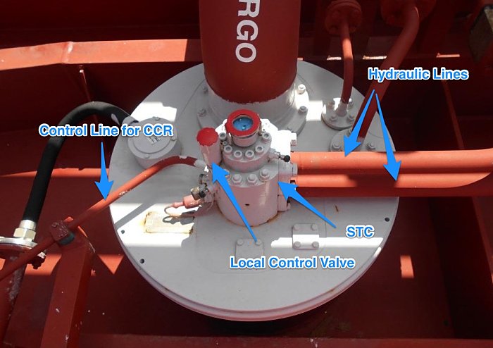
This is exactly what Speed torque controller does. STC is fitted on top plate of the pump on main deck. The Hydraulic oil inlet pass through the STC.
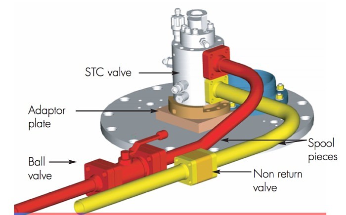
STC of the pump controls the speed of the pump by allowing only the required amount of hydraulic oil to pass through to the hydraulic motor.
STC also prevent the pump to overspeed by controlling the amount of oil to the hydraulic motor of the pump.
There are two ways to control the speed of the pump through STC.
- From the local control on the STC
- From the cargo control room
Local control valve on STC
With local control valve, we can control the speed of the pump locally from the pump itself. This becomes handy during stripping of the tanks or tank cleaning.
Local control valve is a kind of knob located on the STC. When we close the knob (by turning clockwise), the STC passes the oil to the pump.
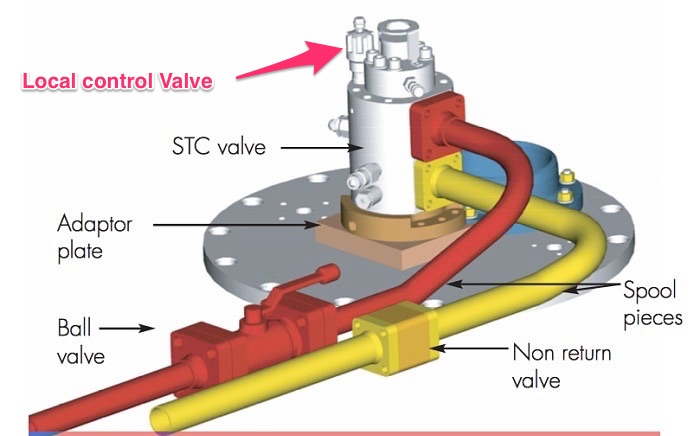
When we open the knob (by turning anti clockwise), the STC bypasses all the oil and nothing goes into the hydraulic motor. Pump stops or do not run in this case.
By partially closing the local control valve, we can adjust the speed of the pump.
Starting the pump from the cargo control room
Speed of the pump (or we can say operation of STC) can also be controlled from cargo control room.
We do this by a lever provided in the cargo control room. Each pump has a lever that connects with the STC of that pump by a hydraulic control line.
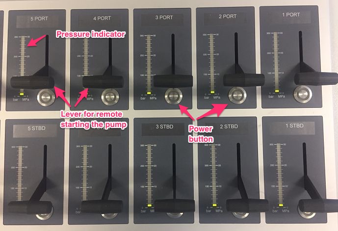
As we push the lever up to start the pump, a signal in form of hydraulic control line pressure goes to the STC.
STC then releases the amount of oil to the hydraulic motor which will be corresponding to the amount to lever lifted.
Here is the actual photo of the STC and pump stack on deck.
Remote start and Local start
Both, the remote start from CCR and local start from the pump location are interconnected.
We cannot start the pump from local control if the pump Lever is not pushed up from the CCR.
Same goes other way around.
If the local control knob is in open position, the pump will not work even when the pump lever is operated from CCR.
So for the pump to operate, STC need to have the signal from both from local control valve as well as remote lever in CCR.
If we need to start the pump from local control
- We open the local control valve by rotating it anti clockwise
- We push the lever up from the CCR
- We operate the pump locally by slowly closing the local control valve
If we have to start the pump from CCR
- We close the local control valve by rotating it clock wise
- From CCR , we push the lever up to start the pump
5. Feed Pumps
For the Framo system to work efficiently, the hydraulic oil used in the system need to be in absolute good condition.
There are few things that can degrade the hydraulic oil quality.
- Moisture ingress due to hydraulic lines being in vacuum due to temperature variation
- Air in the system that can cause vibrations, frothing of the oil etc.
- Small particles that can be inside the oil during filling of hydraulic oil tank or after a maintenance on the system
Feed pump takes care of all of these issues. Here is how.
Feed pump always keep on running, 365 days in a year, 24 hours a day. Feed pump maintains positive pressure in the lines and hydraulic system . It continuously recirculate the oil through entire hydraulic oil system
Usually pressure of more than 5 Bars is maintained in the system even when the system is not in use.
Now when the system is always under positive pressure, the chances of moisture ingress are minimum
Air if any is auto released to the Hydraulic tank while recirculation. Off course if air is still suspected in the system, there is air purging arrangements in the Framo.
And any particles in the system are filtered while feed pump runs the hydraulic oil in recirculation mode. This is because the recirculated oil is made to pass through the filter.
Recirculation of hydraulic oil through feed pump also avoids oil temperature variations at different parts of the hydraulic system.
There is another function that feed pump serves.
It helps in keeping the feed pressure on the suction side of the main hydraulic pump. This means that when high pressure power pack pumps are taking suction from the hydraulic tank, feed pump ensures that there is no negative pressure on the suction side.
Feed pump alarms
One of the feed pumps must always be running when the power packs are not in operation. If the feed pump stops, the “protection pressure Low” alarms will be initiated.
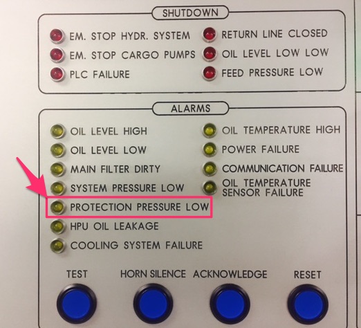
When starting the first main power pack, two feed pumps will automatically start before the power pack is started. This is called high capacity mode of feed system. This is to keep the feed pressure on the suction side of the main hydraulic pump.
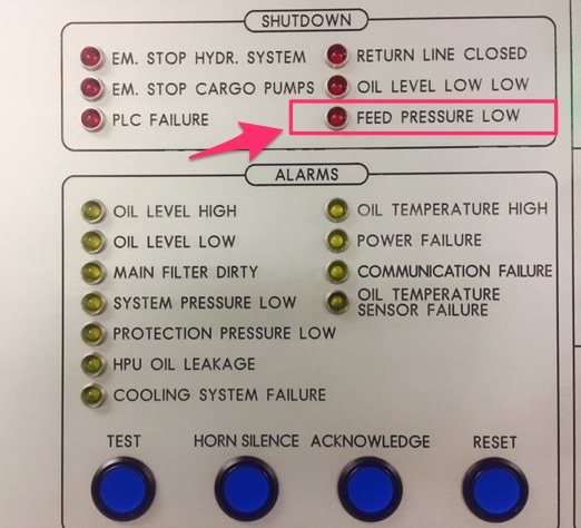
Now let us say that one of the feed pump stops while running in high capacity mode and the power packs are running. In this case the third feed pump will start automatically.
If running signal for the third feed pump is not obtained within 3 seconds, the “feed pressure low” alarm will be initiated and power packs will shut down.
6. Cooling and heating system
Hydraulic oil used in any hydraulic system has a optimum temperature range for use. This is because higher temperature can damage the seals and other components and also it accelerates the degradation of oil.
Hydraulic oil used in Framo system is no exception.
Depending upon the surrounding temperature, the hydraulic oil used in Framo may be below or above this temperature range.
If it is above the optimum range, the oil will need cooling. If it is below the optimum range, it would need heating.
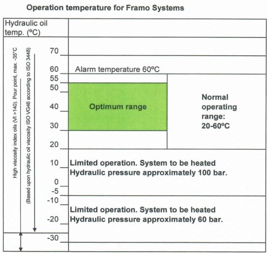
Even if the surrounding tempertaure is within optimum range, the oil temperature will increase during operation.
If the surrounding temperature is below 20 C, we need to open the heating and venting valve for heating with one power pack running. When the oil temperature is well within operating range, other power packs can be started.
Same goes for when the surrounding temperature is higher. The hydraulic oil is made to pass through a oil cooler to cool the oil before delivery on deck.
The cooling water inlet valve is automatically controlled. It will open at hydraulic oil temperature above 50 C and will close when temperature decreases to below 30 C.
The “high oil temperature alarm will activate if the oil temperature is above 60 C.
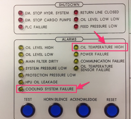
When oil temperature reaches 70 C, the power packs will trip.
7. Emergency Stops
One final thing (among many other) that the operator of the Framo pumps need to know is about “Emergency stops” for the pumps.
These are the push buttons installed at different locations. When pressed, the hydraulic system will trip immidiately.
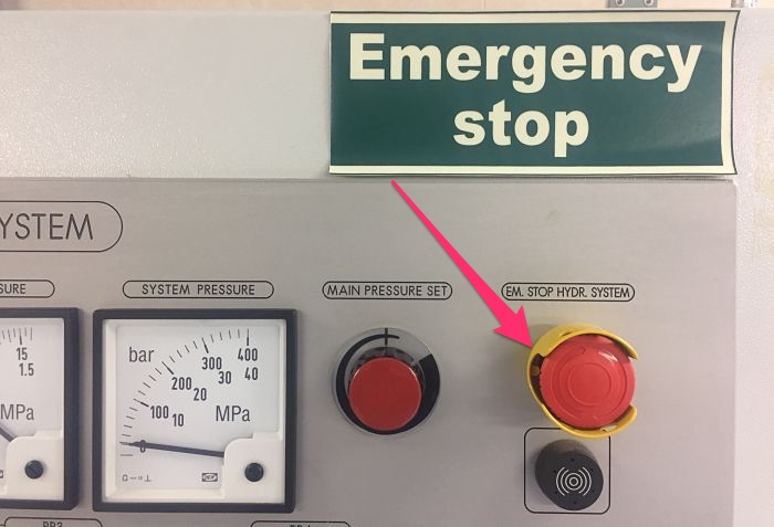
The common locations for these emergency stops are
- Cargo control room
- Manifold port side
- Manifold starboard side
- At the power pack location
On each ship, there could be few locations for emergency stop for Hydraulic system. We must know all of these locations.
Conclusion
Submersible pumps on board tankers is the first choice for the ship owners because of various advantages these offer.
This is particularly the case with chemical and product MR and LR tankers.
Framo is leader among the submersible pumps fitted on board tankers. For anyone working on tankers, this makes the thorough knowledge of the Framo system a necessity.

![[Click here for larger view]](https://www.myseatime.com/blogadm/wp-content/uploads/2017/03/purging.png)